
- Forums
- Satellite TV receivers & systems support forums
- DISH SETUP: Single sat, Multi-Sat & Motorised
You are using an out of date browser. It may not display this or other websites correctly.
You should upgrade or use an alternative browser.
You should upgrade or use an alternative browser.
mechanical polarotor
- Thread starter dreambox1959
- Start date

dreambox1959
Specialist Contributor
- My Satellite Setup
- Octagon SF8008 - technomate 7100
- My Location
- france
I have just carried out real tests on my EGIS
I used a PLL universal LNB.
the offset applied (adjustable) is that of satlex.be .
I still have to find a case to protect the electronic board and the motor.


I used a PLL universal LNB.
the offset applied (adjustable) is that of satlex.be .
I still have to find a case to protect the electronic board and the motor.
dreambox1959
Specialist Contributor
- My Satellite Setup
- Octagon SF8008 - technomate 7100
- My Location
- france
i work again on my polar system .
I designed my system based on the same principle as DiSEqC rotors (LNB changers).
The assembly is powered by the 18V cable, and the controls are in DiSEqC format for adjusting the skew.
I've included a 0° initialization system upon power-up.
This device is compatible with universal (H/V) LNBs or older single-polarity LNBs.
The position is adjustable between +90° and -90°.

I designed my system based on the same principle as DiSEqC rotors (LNB changers).
The assembly is powered by the 18V cable, and the controls are in DiSEqC format for adjusting the skew.
I've included a 0° initialization system upon power-up.
This device is compatible with universal (H/V) LNBs or older single-polarity LNBs.
The position is adjustable between +90° and -90°.
pitussat
Member
- My Satellite Setup
- dishes: CM 3m SMC,-Prodelin 3m SMC old version ,CM 1,80m SMC, Fibo 1,2m, Wavefrontier T90
receivers;>30 different types.+ TBS5925/6925 ETC
- My Location
- belluno, Italy
i got this lnb, it is for VSAT application c120 for feedhorn port, wr51 for tx side 14GHz ,but can pass 11GHz band
dreambox1959
Specialist Contributor
- My Satellite Setup
- Octagon SF8008 - technomate 7100
- My Location
- france
today i build my mechanical polarotor for me and for an italian friend .
i drawn a board to decode an non-refenced diseqc command , this order send the skew value.
my board decode and manage a 18V motor (with pulses) to turn a wave guide made of aluminium tube .
The tube is guided by nylon parts and rotated by a toothed pulley.A cam is fixed to the pulley to automatically find the 0° point.
The 18V power supply is taken from the LNB-Changer cable (the changer function is always active).
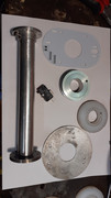
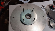
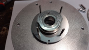
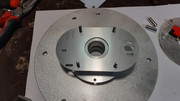
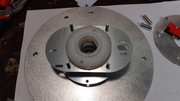
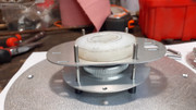
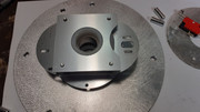
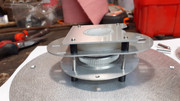
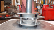
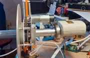
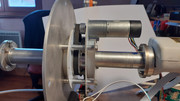
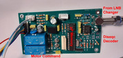
i drawn a board to decode an non-refenced diseqc command , this order send the skew value.
my board decode and manage a 18V motor (with pulses) to turn a wave guide made of aluminium tube .
The tube is guided by nylon parts and rotated by a toothed pulley.A cam is fixed to the pulley to automatically find the 0° point.
The 18V power supply is taken from the LNB-Changer cable (the changer function is always active).
Last edited:
today i build my mechanical polarotor for me and for an italian friend .
i drawn a board to decode an non-refenced diseqc command , this order send the skew value.
my board decode and manage a 18V motor (with pulses) to turn a wave guide made of aluminium tube .
The tube is guided by nylon parts and rotated by a toothed pulley.A cam is fixed to the pulley to automatically find the 0° point.
The 18V power supply is taken from the LNB-Changer cable (the changer function is always active).
Outstanding work, truly excellent, well done.
Couple of questions if you can please help?
1. Have you a picture of the unit mounted on a dish please ?
2. Can the polarotor be powered by your positioner or would the positioner need a modification ?
yoghy67
Member
- My Satellite Setup
- Prodelin 180 - two actuators 36 inch for AZ and 24 inch for EL - LNB revolver by Trust with 4 lnb (Inverto black ultra, LNB Titanium C band LNBF C238 + AV comm) - JPC positioner by Dreambox1957 with two servo motors to control skew. Octagon SF8008
- My Location
- Italy - La Spezia
Wonderful !
dreambox1959
Specialist Contributor
- My Satellite Setup
- Octagon SF8008 - technomate 7100
- My Location
- france
1-soonOutstanding work, truly excellent, well done.
Couple of questions if you can please help?
1. Have you a picture of the unit mounted on a dish please ?
2. Can the polarotor be powered by your positioner or would the positioner need a modification ?
2- polarotor is powered with 18V (motor is 24V) ,power is taken from either lnb changer ouput or positioner internal wire to rear connector .
i made 2 firmware : use only lnb changer cable (power + command) or 18V from posi + skew command (5v).
the second one is ready to use with all posi !! the first one need an update for the posi firmware .
pitussat
Member
- My Satellite Setup
- dishes: CM 3m SMC,-Prodelin 3m SMC old version ,CM 1,80m SMC, Fibo 1,2m, Wavefrontier T90
receivers;>30 different types.+ TBS5925/6925 ETC
- My Location
- belluno, Italy
Amazing job!1-soon
2- polarotor is powered with 18V (motor is 24V) ,power is taken from either lnb changer ouput or positioner internal wire to rear connector .
i made 2 firmware : use only lnb changer cable (power + command) or 18V from posi + skew command (5v).
the second one is ready to use with all posi !! the first one need an update for the posi firmware .
dreambox1959
Specialist Contributor
- My Satellite Setup
- Octagon SF8008 - technomate 7100
- My Location
- france
The origin of this project is the need to use a universal LNB with an EGIS motor (AZ EL).
During azimuth rotation, the LNB must tilt approximately 45° at its east and west ends.
I copied the principle of DiSEqC motors:
- Command transmitted via 22 kHz
- 18V power supply provided by the cable
- Automatic alignment by a cam at the 0° point.
I had to fabricate many plastic and aluminum parts on a lathe.
I also used JLC aluminum printed circuit boards.
I created an entire software package for my positioner on a small circuit board.
I haven't calculated the cost, but it's not negligible; however, it was a very motivating challenge.
During azimuth rotation, the LNB must tilt approximately 45° at its east and west ends.
I copied the principle of DiSEqC motors:
- Command transmitted via 22 kHz
- 18V power supply provided by the cable
- Automatic alignment by a cam at the 0° point.
I had to fabricate many plastic and aluminum parts on a lathe.
I also used JLC aluminum printed circuit boards.
I created an entire software package for my positioner on a small circuit board.
I haven't calculated the cost, but it's not negligible; however, it was a very motivating challenge.

Satfaca
Specialist Contributor
- My Satellite Setup
- Orbitron SX-10 310 cm + H2H motor + ADL RP2-CPOR feed
Prodelin PFA 240 cm + EGIS ProfiTracker + Chaparral PR1 Ku feed
Octagon SF8008 (Twin & Combo) + TBS 6983
Chaparral M140 + Echostar DVR-7000 HDD + Lyngbox
- My Location
- Melmac
Could you possibly "create" the same for Ka band?

- My Satellite Setup
- A little less analogue, and a lot more crap.
- My Location
- UK
To receive all up there on Ka band will require four polarities and at least two LNBs to capture the various bands.Could you possibly "create" the same for Ka band?
I would suspect there is a depolarising mechanical waveguide out there for the mid-band frequency but I've not seen one in the flesh.

dreamsat
Specialist Contributor
- My Satellite Setup
- 2,20m Kathrein, 3,7m Andrew, KU,KA,C,C-Ext. LNBs
- My Location
- germany
Yes, depolarizers exist. Without one, it's essentially pointless. Unfortunately, all polarization states are covered in the Ka-band, so H, V, L, and R depolarizers are needed.
I modified Gilat LNBs so that two bands are always possible and both linear and circular operation is possible. They work very well.
I modified Gilat LNBs so that two bands are always possible and both linear and circular operation is possible. They work very well.
dreambox1959
Specialist Contributor
- My Satellite Setup
- Octagon SF8008 - technomate 7100
- My Location
- france
My solution is suitable for an installation where the Ku band is in the center (I put the C band next to it).Could you possibly "create" the same for Ka band?
For the Ka band (which I don't have!), you just need to use a smaller waveguide, and why not two parallel waveguides (one linear polarized, the other circular)?
But there are four Ka bands!
So which band should you choose?
dreambox1959
Specialist Contributor
- My Satellite Setup
- Octagon SF8008 - technomate 7100
- My Location
- france
I found aluminum tubing with an inner diameter of 10.6mm, which corresponds to the Ka band values.
But I only see LNBs with a WR42 input.
Are there Ka feeds, orthomode feeds, etc.?
If anyone has the dimensions of a Ka feed for PF, I'd be interested.
I ordered a SAORSAT LNB with the intention of modifying it!
But I only see LNBs with a WR42 input.
Are there Ka feeds, orthomode feeds, etc.?
If anyone has the dimensions of a Ka feed for PF, I'd be interested.
I ordered a SAORSAT LNB with the intention of modifying it!
dreambox1959
Specialist Contributor
- My Satellite Setup
- Octagon SF8008 - technomate 7100
- My Location
- france
does this device can be useful with SAORSAT lnb ?
maybe it can be adjust to change OL ?

maybe it can be adjust to change OL ?
Miika
Member
- My Satellite Setup
- MM9800S, TBS5925, Openbox S3 Mini II. Many DVB-T/T2 boxes.
8+ sat-dishes and even more LNBs. 80E to 30W at the moment (90E to 45W possible).
Small DVB-T transmitter for experiments.
- My Location
- Estonia
It is for Directv original Ka-band multi-LNB-s only. It upconverts Ka-band output (250-750 MHz) to receiver's 1650 - 2150 MHz range.
dreambox1959
Specialist Contributor
- My Satellite Setup
- Octagon SF8008 - technomate 7100
- My Location
- france
With the motorized polarizer, it can be used with two types of mounts and two types of LNBs:
- Equatorial mount and AZ-EL mount (Egis).
- Dual-polarization LNB (Universal) and single-polarization LNB (Norsat).
1- Universal LNB on a polar mount with or without correction.
2- Universal LNB on an AZ-EL mount (Egis) with correction.
3- Single-polarization LNB on a polar mount with horizontal and vertical correction.
4- Single-polarization LNB on an AZ-EL mount (Egis) with horizontal and vertical correction.
- Equatorial mount and AZ-EL mount (Egis).
- Dual-polarization LNB (Universal) and single-polarization LNB (Norsat).
1- Universal LNB on a polar mount with or without correction.
2- Universal LNB on an AZ-EL mount (Egis) with correction.
3- Single-polarization LNB on a polar mount with horizontal and vertical correction.
4- Single-polarization LNB on an AZ-EL mount (Egis) with horizontal and vertical correction.
- My Satellite Setup
- A little less analogue, and a lot more crap.
- My Location
- UK
Whilst for an offset dish, the dimensions within the last page may be of use.I found aluminum tubing with an inner diameter of 10.6mm, which corresponds to the Ka band values.
But I only see LNBs with a WR42 input.
Are there Ka feeds, orthomode feeds, etc.?
If anyone has the dimensions of a Ka feed for PF, I'd be interested.
I ordered a SAORSAT LNB with the intention of modifying it!
Btw if you are looking to fit the Saorsat LNB on the end the WR42 suffix is irrelevant
dreambox1959
Specialist Contributor
- My Satellite Setup
- Octagon SF8008 - technomate 7100
- My Location
- france
I redesigned my interface board to mount it on the LNB bracket.
I designed it to support two types of interfaces:
either for an EGIS motor (24V power and Skew signal)
or for a DiSEqC controller (of my own design) connected to the line intended for the LNB changer (18V power).

I designed it to support two types of interfaces:
either for an EGIS motor (24V power and Skew signal)
or for a DiSEqC controller (of my own design) connected to the line intended for the LNB changer (18V power).

