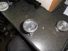
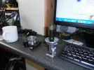
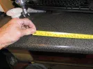
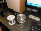
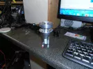
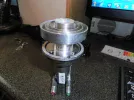
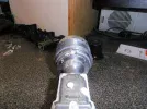
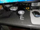
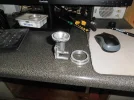
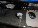
Restoring a working antique dish to full functionality..

Will post tomorrow first class mail, you might get it Saturday.

 
Thanx CH feed arrived with this mornings post....
First job will be seeing if it fits nicely on the alcoa....if the fekkin rain ever stops that is.
drop me a PM on payment deyails.
rgds
 
See if it works first, you might be sending it back.
 
I doubt I would want to return it...
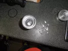
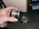
Already removed the red cap from the bullseye...and removed the second stepped scalar from the bullseye with snipe nosed pliers.
dremel next to remove the ally burrs...but as you can see from the pix the c120 feed on your feed fits snuggly inside the bullseye mouth.
I may have to fit a small section of pipe to make up the missing waveguide ..but potentially the 4 holes in the c120 flange could be continued through the bullseye flange allowing them to be bolted together...trapping the small pipe section between.
hope that makes sense..
 

Attachments

  • P1010013.webp
    P1010013.webp
    421.6 KB · Views: 19
  • P1010014.webp
    P1010014.webp
    812.1 KB · Views: 19
  • P1010015.webp
    P1010015.webp
    892.7 KB · Views: 16
  • P1010016.webp
    P1010016.webp
    1.4 MB · Views: 20
The first offset scalar ring the one under the red cap now removed ..with a hacksaw and surface smoothed with glasspaper.
I daresay this one didn't need to be removed..
Advantages...less bulk
better access to smooth that second rind removed with pliers..
better range of movement if clamped at the join on the dish mount.
 

Attachments

  • P1010017.webp
    P1010017.webp
    837.2 KB · Views: 21
Now for a tricky bit..
replacing the missing waveguide..
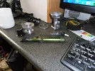
The tube needs to be ideally Aluminium int diam 17mm ext diameter 20mm - ish
Of course such ally tube is unobtainium...except it sort of isn't ..
enter the sacrificial mechanical solder pump.
easily replaced for about £2...so why not
 

Attachments

  • P1010020.webp
    P1010020.webp
    1.1 MB · Views: 17
  • P1010018.webp
    P1010018.webp
    796.5 KB · Views: 19
Looking good, by the way what is the interior diameter of the Bullseye cavity ?

You may find cutting the scalar off entirely and filing to sleeve into the new feed improves the transfer (I recall there was a performance drop at 12GHz when cavity length was over 8cms), hitting the exact focal point is the main criteria though, seconded by illumination of the entire parabola.
 
Now for a tricky bit..
replacing the missing waveguide..
The tube needs to be ideally Aluminium int diam 17mm ext diameter 20mm - ish
Of course such ally tube is unobtainium...except it sort of isn't ..
enter the sacrificial mechanical solder pump.
easily replaced for about £2...so why not
17mm would push the centre frequency up to 17GHz, slightly outside the Ku band.
 
I would usually sleeve out feeds with a section of coke or cider cans, very easy (to cut your fingers)
 
Looking good, by the way what is the interior diameter of the Bullseye cavity ?

You may find cutting the scalar off entirely and filing to sleeve into the new feed improves the transfer (I recall there was a performance drop at 12GHz when cavity length was over 8cms), hitting the exact focal point is the main criteria though, seconded by illumination of the entire parabola.
Cant tell you exactly Stephen...dont have calipers long enough or thin enough to reach inside the bullseye throat.
What I can say is that the ally tube from the solder sucker wont slide into it but will stand upright at the point the throat narrows so less than 20mm but not by much.
so likely 18mm diameter. ?
Distance from first throat antenna probe (bullseye) to end of CH waveguide when fitted will be approx 8.5cm
Distance from rear of bullseye waveguide chamber to end of CH feed will be 9.5cm approx
do you think this will be close enough ?
Thinning the ally at various points of contact may gain me a few more mm if needed...thus shortening the overall length of the waveguide...but we are talking 4mm possibly 5mm at most.
ie ..the thickness of the c120 feed flange you provided is 6mm so could be reduced by say 4mm without losing rigidity and clampability.

having removed the burrs from the cut solder pump tube the internal dameter was measured again and is closer to 17.5mm not 17mm
a step in the right direction....
 
Last edited:
In light of the accuracy needed for this project I treated myself to some better calipers from Amazon..
They should be here tomorrow and much better than struggling with my cheapo plastic ones.

Preciva Digital Vernier Caliper, USB-C Rechargeable 150mm / 6inch Stainless Steel Calipers Measuring Tool – IP54 Water-Resistant with Large LCD Display, MM/IN Conversion, Lock & Zero Function​

 
In light of the accuracy needed for this project I treated myself to some better calipers from Amazon..
They should be here tomorrow and much better than struggling with my cheapo plastic ones.

Preciva Digital Vernier Caliper, USB-C Rechargeable 150mm / 6inch Stainless Steel Calipers Measuring Tool – IP54 Water-Resistant with Large LCD Display, MM/IN Conversion, Lock & Zero Function​

In the meantime you could cut a piece of solder to the length that just slides into the throat, then measure with a standard ruler.
 
Gone as far as I could today...
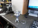
Drilled the M2 holes to clamp CH feed to Bullseye ...
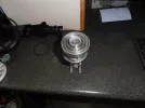
used the aluminium circle I'd removed earlier as a spacer to make up the perimeter gap around the CH feed temporarily ..this will be replaced with a rubber gasket.
Once assembled I took Stephens advice and passed a piece of solder down inside the new assembly until it touched bottom the bent it over to mark it ..
The solder length checks in at 9.8cm feed end to base of lnb cavity.

No addtional internal waveguide added between feed and lnb at this point.
 

Attachments

  • P1010025.webp
    P1010025.webp
    1.1 MB · Views: 31
  • P1010024.webp
    P1010024.webp
    728.8 KB · Views: 22
  • P1010023.webp
    P1010023.webp
    738.5 KB · Views: 23
  • P1010022.webp
    P1010022.webp
    686.4 KB · Views: 26
  • P1010021.webp
    P1010021.webp
    950.4 KB · Views: 43
Gone as far as I could today...
Drilled the M2 holes to clamp CH feed to Bullseye ...
used the aluminium circle I'd removed earlier as a spacer to make up the perimeter gap around the CH feed temporarily ..this will be replaced with a rubber gasket.
Once assembled I took Stephens advice and passed a piece of solder down inside the new assembly until it touched bottom the bent it over to mark it ..
The solder length checks in at 9.8cm feed end to base of lnb cavity.

No addtional internal waveguide added between feed and lnb at this point.
I meant the throat diameter.
 
Might as well wait until tomorrow for that Stephen...
I dont want to open her up again today.
cheers
 
Of course, I wasn't expecting the feed to arrive the following day, based on the RM paperwork
 
Whilst waiting for the calipers to arrive I decided to tackle the waveguide depth which was previously 9.8cm
We need to be in the 7 to 8cm range..
So out came the hacksaw again...and an hour later the offset feed is reduced again to the point at which the flaring reaches 3cm diameter..
This still leaves enough flange to be used to bolt the 2 items together..
It also allow me to properly measure throat diameter once those calipers arrive.
And the real purpose of this process ..reduces waveguide depth to 7.8cm (the sweet spot).
and finally ...it removes even more cast aluminium bulk...thus the sleeve piece can be even shorter.
At this point the short 'sleeve' could be made by inserting a small section of pipe into the sloping mouth of the bullseye and pouring silver epoxy into the space around the centre pipe ...and that is the route I would take if silver epoxy wasn't so ridiculously expensive.
perhaps there is a cheaper alternative I'm unaware of ?
Must be pourable/moldable and conductive when cured ?
cest la vie
rgds
Just discovered that

Aluminum Metal Repair Epoxy Adhesive Glue 1 Set Strong Bond Machinable Sandable​

can be got from China at £3 approx.....but no idea if this is truely ally ...and conductive.
Anyone used it ...???
Just asked google AI :-
Properties of Standard Metal Repair Epoxy
    • Strong Bond: Creates a rigid, high-strength structural hold on aluminum, iron, and steel without needing high heat or welding tools. [1]
    Electrical Insulation: Standard epoxy resins act as electrical insulators. They block electricity rather than conduct it

  • If your repair specifically requires electrical conductivity (such as fixing circuit traces or electronic grounding tabs), standard metal repair epoxy will not work. Instead, you must use a specialized electrically conductive adhesive infused with metal particles, such as MG Chemicals 8331D Silver Conductive Epoxy Adhesive
 

Attachments

  • P1010026.webp
    P1010026.webp
    1.1 MB · Views: 17
  • P1010027.webp
    P1010027.webp
    1.1 MB · Views: 18
  • P1010028.webp
    P1010028.webp
    1,011.7 KB · Views: 27
Last edited:
If I had known that was your plan, removing the outer scalar rings completely and perhaps turn (or file) down the cylinder to fit inside the PF feed would keep the electrical connectivity.

(In part the reason for asking about the Bullseye measurements).
 
Last edited:
It wasn't my plan initially to remove so much bullseye feed Stephen ..but after discovering anything longer than 8cm (waveguide wise) results in losses I changed my approach.
It _was_ however always my intention th leave enough of the original offset waveguide to be used as a flange to bolt to the C120 feed.
Silver epoxy is afaik the only real conductive epoxy but at £130 for 14mg ...
err no thanx.
 
Last edited:
Back
Top