Advice Needed Receivers with the lowest Symbol Rate?

Just in case anyone was wondering..
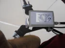
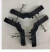
I haven't abandoned the project...but I an waiting to receive one of these..see picture.
Thinner lighter and made of plastic not metal.
I'm sure I can adapt this for my needs...
advantages ..less metal occluding the beam transit plus ajustable diameter at mount point from 65mm C band ..down to 23mm.
Thus a greater chance of easily hitting that sweet spot.
In the meantime I've switched my attention to fitting a growlight in my greenhouse....late in the season but I still have 10 galia melons to somehow ripen before winter arrives.
 

Attachments
  • spider.webp
    spider.webp
    43.4 KB · Views: 50
Last edited:
Just in case anyone was wondering..
I haven't abandoned the project...but I an waiting to receive one of these..see picture.
Thinner lighter and made of plastic not metal.
I'm sure I can adapt this for my needs...
advantages ..less metal occluding the beam transit plus ajustable diameter at mount point from 65mm C band ..down to 23mm.
Thus a greater chance of easily hitting that sweet spot.
In the meantime I've switched my attention to fitting a growlight in my greenhouse....late in the season but I still have 10 galia melons to somehow ripen before winter arrives.
You could have had one off me VS, I have about 4 of them spare..
 
Last edited by a moderator:
appreciated mate....but it's on order now
I just hope it will be easily adaptable to Christine.
 
Another tool to add to my collection.
Not bad for £8
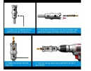
Ordered a
23mm tungsten carbide teeth, 3-cutter design, pilot drill included, storage case, for sheet plate pipe work

The pilot drill is removeable
I'm hoping this will clean up the crude attempt I made at boring out the cast aluminium throat of the lnb with a wood spade bit.
chances are I can find a way to do this by hand rather than with a drill now that most of the material was already removed.
What have I got to lose ?

​


Attachments

  • 23mm hole cutter.webp
    23mm hole cutter.webp
    31.9 KB · Views: 43
Last edited:
Another tool to add to my collection.
Not bad for £8
Ordered a
23mm tungsten carbide teeth, 3-cutter design, pilot drill included, storage case, for sheet plate pipe work

The pilot drill is removeable
I'm hoping this will clean up the crude attempt I made at boring out the cast aluminium throat of the lnb with a wood spade bit.
chances are I can find a way to do this by hand rather than with a drill now that most of the material was already removed.
What have I got to lose ?

​

You may be thinking too hard. Get the boresight centred (does the Alcoa have the removeable centre plate ?)

If so take it out and drill a hole in the polarmount for camera picturs from behind the dish.

When did you last string the panels (look down the rim first , ooerrr)

PS. FAO Flippi, will try to move Evan's latest quest for low symbol rate stuff onto a new thread when I get time.
 
Evan, what is the manufacturers specification of Christine , f/D dation and gain at 11GHz ?
 
I'll have a read through the limited documentation I have and hope the FD is in there..
Not sure gain will be specified tho'...simply because of her age..
After all she was designed for C band so may never have published gain at 11ghz.

As to the centre panel ..yes it is removeable ..in fact only today I found it resprayed and re-fitted.
I did think about mounting a laser pen at the lnb mount point and producing a green dot on the dish..which is why I refitted the centre panel.
Problem is ..no idea how 'true' laser pointers are ?

The last time she was strung was when I took the whole thing down some years ago..
Resprayed and regreased the mount new 15cm thick pole set in the ground...
It was at least a 2 man job.
I had space to do it then after shifting all my furniture.
I was a lot younger ...and I remember her being heavy even then.
I could string her in situe...but no idea how efective that would be.

Nothing spec wise in the manual.
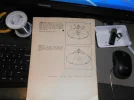
great assembly instructions for both dish and mount...but no real spec ...just a few diagrams such as this :-
 

Attachments

  • P1010056.webp
    P1010056.webp
    403.6 KB · Views: 37
Last edited:
OK, laser pen is secondary, but a look at the rim will provide a view from the ground and quick idea if anything has shifted.

Christine might have had gravity working against her all these years, she might just need a strip and good shake.
 
OK, laser pen is secondary, but a look at the rim will provide a view from the ground and quick idea if anything has shifted.

Christine might have had gravity working against her all these years, she might just need a strip and good shake.
I may well invest in a ball of string and string her in situe..
Should give a rough idea maybe ?
I dont know how rare my assembly instructions are but might scan them for upload later this year.
cheers buddy

..and yes I might well be overthinking or overcompensating....but my philosophy fwiw is ..you can never have too many tools.
lol
 
Post a few pictures of Christine side on first, no need to move the cat yet.

Having looked at your 'down the orifice' picture of earlier the feed could be a couple of degrees away from centre meaning the feed might be in a Ku quiet area.
 
Last edited:
what have I learned today...?
took posession of a universal high gain ku prime focus lnb (new old stock)
now I know this wont lock at low SR at low signal levels.
...but much easier to mount and slide in and out.
It has 4 scalar rings unlike the CH c120 feed which has 3
Took some measurements with a metal tape...and established I could get a lock on 11996 H (fta mux)
It would appear the sweet spot is around 83 cm (32.6 inches) to the front of the scalar rings
or 81cm to the tip of the waveguide (31.8 inches)
This tallies nicely with the dish manual fd (31.5 inches)
also this is not accounting for any skew ajustment.
this lnb does not perform as well as the bullseye ..easily 2db less gain and of course will not lock low SR
I do get about a cm of distance manoeuver around the 'sweet spot' where little is gained or lost.
I'll put this down to christines old age and gravity over time.
ie ..she aint perfect any longer....but still pretty good for her age.
 

Attachments

  • P1010057.webp
    P1010057.webp
    248 KB · Views: 23
  • P1010058.webp
    P1010058.webp
    234.2 KB · Views: 30
Last edited:
Post a few pictures of Christine side on first, no need to move the cat yet.

Having looked at your 'down the orifice' picture of earlier the feed coulld be a couple of degrees away from centre meaning the feed might be is a Ku quiet area.
I suspect her alignment may indeed be little out Stephen but not by a massive amount.
Also I fully intend to knock up some sort of laser to mount at the spider ...but may wait until I have the new spider to try.
 
Last edited:
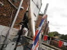
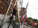
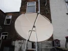
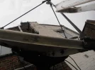
Ok some dish shots ..whilst the cat (peppa) is having her lunch.
Sadly I dont have 360 deg access ..so hopefully these will do CH.
There is a definate oddity bottom right petal.
even I can see it and my eyes a shyte these days.
maybe something fixable with a block of wood and a hammer as it only appears to be the lip ?
 

Attachments

  • P1010001.webp
    P1010001.webp
    524.5 KB · Views: 27
  • P1010002.webp
    P1010002.webp
    647.9 KB · Views: 29
  • P1010003.webp
    P1010003.webp
    351.1 KB · Views: 24
  • P1010004.webp
    P1010004.webp
    297.2 KB · Views: 23
  • P1010005.webp
    P1010005.webp
    202.6 KB · Views: 17
Last edited:
Picture 2 says it all, she has a wobbly bottom and top. Petalised dishes are unfortunately subject to warpage (as are women)


The far rim should be in line with the front rim, no need to string yet but the next step is to undo all bolts between reflectors a bit, elevate as high as you can at 0 degrees/top lip as close to the wall as possible, then shake like hell before tightening everything back again in the same position.

Only when the cat is otherwise busy of course (and you have a handy helper)

No need for a laser thingy, this is all old school
 
Last edited:
Forgot to mention, the critical bolts to the polarmount will also need undoing for Christine to revert to a beauty.
 
Looking back

 
I can totally understand how the outer sections of the petals could move or even change position over time ...but I can't get my head around the area of the dish in the centre area inside the perimeter of the polar mount ring _could_ move once bolted up as it would require moving aluminium bolted to a steel ring as thick and heavy as scaffold pole.
seems so unlikley to have moved at all...wheras the petals beyond the polar mount ring would be subject to wind or even gravity over time...only having the aluminiums shape to keep structure ?

I'm gonna fire up the scanner and scan what I have of the 2 manuals both dish and polar mount.
The polar mount on its own required 2 men to lift into place with frequent breaks ..it was so heavy.
But then I guess the height of the pole was a factor..
6 foot above ground and 2 foot into the ground....so it had to be lifted 6 foot in the air.
 
Last edited:
Ok..happy this will now be preserved..
So for anyone interested :- have at it.
zip files not accepted so a link to my dropbox
lol
 
I can totally understand how the outer sections of the petals could move or even change position over time ...but I can't get my head around the area of the dish in the centre area inside the perimeter of the polar mount ring _could_ move once bolted up as it would require moving aluminium bolted to a steel ring as thick and heavy as scaffold pole.
seems so unlikley to have moved at all...wheras the petals beyond the polar mount ring would be subject to wind or even gravity over time...only having the aluminiums shape to keep structure ?
Christine could have been warped during the installation, earlier forum images might show it though I'm sure somebody would have pointed it out.

It is also possible the extender panels had something to do with the error in shape.

What is not in doubt is the Ku band performance will be compromised by the current shape. Most petalised dishes will have tolerances built into the holes on the polar ring to enable the panels to settle down correctly before nipping up the bolts.


Here is the general adjustment for Prodelin PF dishes, though the installation of the refector is supposed to be carried out face down on a level surface, not always available on a 4.5m

Use thin cord across the reflector diameter from rim to rim, at four places. One
end of each string should be taped to the rim just to one side of the seam
between two petals. The other end should be fastened 180 degrees opposite. All
four strings should lightly touch where they cross at the center. The distance
from center of the reflector (hub to plate) to the strings should be 16.09.
3. If the reflector does not check out as described above within approximately a
1/4", reflector adjustment may be done. Identify the point on the rim that is either
high or low. Loosen the four bolts on the long and short angle brace behind the
radial line of the reflector. Gently push or pull on the reflector rim until it is
brought into position. While one installer holds the rim, the other should tighten
all the brace bolts fully. Repeat this process as required, loosening and
tightening only one set of braces at a time.


And on AI
The Prodelin Series 1374 3.7-meter antenna features an 8-panel, compression-molded glass fiber reinforced polyester (SMC) reflector reflector. When assembling or performing a "shakedown" panel alignment (historically referred to as a mechanical compliance check or settling process), achieving high surface accuracy is essential to prevent sidelobe degradation and maximize signal gain—especially for Ku-band operations. [1, 2, 3]
The structural alignment checklist and shakedown process for the Prodelin 1374 includes:

1. Reflector Pre-Assembly & Shakedown Setup


    • Loose Hardware First: When bolting the 8 individual petals to the central hub/support frame, keep all seam and radial hardware finger-tight. Do not torque bolts down section by section. [1]
  • The "Shakedown" Action: Physically grasp the outer rims of opposing panels and give the un-torqued reflector structure a gentle shake/jolt. This allows the interchangeable SMC panels to naturally seek their factory-molded datum points and settle flush along the connecting seams
 
Last edited:
The extender panels having had an effect I totally understand..
probably responsible for that ebge anomaly bottom right petal.
They have sadly gone now ...and the original dish edge plates are lost to time (aluminium 2 hole strips about 14cm long with 2 holes spaced about 10mm apart) .
Part 9 in the manual.....unless of course I can find them again amongst all my junk.
They were removed when the extender panels were fitted....so looks like I at least have new replacements to make.
rgds
 
Last edited:
Back
Top