Converting AZ-El mount to Non-motorised polar mount

The Astra satellites (19E, 23E and 28E) have a preskew of 7.5 degrees.
The Eutelsat satellites (13E and others) have a preskew of 3.535 degrees.

In a motorized setup, it is customary to discard this preskew, and assume skew = 0 towards due south.
While rotating the dish, the skew of you setup rotates with it, so that the endresult skew again about matches the skew of the chosen satellite.

Mentioned a few years back (there was also the Telecom satellite offsets from earlier)


'about matches'

A 3.5 degree error would be visible in all but the cheapest spectrum analysers when testing a similiar magnitude of sinal on the opposite polarity. Professional installers would usually be taught to find the null point/minimum interference from the opposite polarisation on a fixed satellite system.

A 7 degree offset error in mathematics would equate to approximately 12% less effective signal, or 0.5dB
 
The weird thing is: The charts with modified motor angles, that I found on the internet, all use modified angles that are based on the declination fit for invisible satellites (below the horizon); using what I call the 0-90 degrees fit, or the 0-180 degrees fit.
So that even when you are at latitude 80, the forward axis tilt in the charts is bigger than 0.20, though for the small range of visible satellites the needed forward axis tilt actually is only maximally 0.03!
So most/all charts on the internet overcompensate. @B.J. alias @wejones (great advocate for the modified angles) hinted to that, already.
I made new calculations for a 0-horizon fit chart (I used that chart in the post above). I guess that approach still overcompensates a little bit, for the visible part of the arc, but I assume it is already much better than the other charts. Though I have never further calculated on that for the inbetween parts of the visible arc.

Thankfully all is about just tenths of a degree, so being a bit off is not a very big problem.

Greetz,
A33
So I wrote a program to compute it myself a few years ago. It computes the optimal angles and can visualize the result.
What matters is the elevation error (how much does dish point above or below the clark belt) which is about 0.1 degree worst case.
This is for a total azimuth coverage of 110 degrees. My 1.2m dish has a 3dB beamwidth of about 1.5 degree. The errors are 15 times smaller,
even worst case. From a practical point of view, an error of 0.5 degree has a measurable impact (about 0.5dB ). So 0.1 degree error
should have no significant effect.

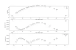
The top graph shows how far the satellites are above the horizon (clark) overlayed with the arc the dish points too.
The difference is almost unnoticable, but the second two graphs show it in detail. They show that for azimuth it can better to slightly (up to 0.1degree) move away from the computed "usals" angle. Effectively this slightly lowers (or raises) the dish causing the vertical error to decrease and the horizontal error to go up until the best compromise is reached.

For a 1.2m dish, there is not much practical difference. For a 1.8m dish, I expect compute errors to only have an impact of less than 0.5dB even over this very wide arc range. In any case it requires 1.5 times more accurate pointing.
angles.webp

One problem I encountered was that the rotation axis on my diseqc motor seemed to be slightly off spec, so I needed to correct the declination of the dish by about 0.3 (?) degree. It took me a while before I actually realized this.

You need a good quality inclinometer to be able to measure this, or make your own inclinometer using some card board, some thin thread and a little weight. The latter is actually the most accurate.

At one point, a storm also causes the dish to move about 1 degree w.r.t. the rotor axis. That is easy to correct in software (just add or subtract
1 degree from the computed angles - neumoDVB allows this). I could have realigned the dish, but I didn't.
Then recently another storm blew it back in exactly the correct position. Haha...
I then slightly fasten the bolts a bit more.

Actually it may not be a bad idea to not fasten those bolts too strongly: a strong gust of wind then puts less pressure on the gears of the rotor, risking less damage at the expense of an easy to fix azimuth error problem. My 1.2m dish is already above the maximum recommended size for a diseqc positioner, but the whole system has survived for 10 years, perhaps also because the dish is lightweight. At some point the rotor developed some slack, but that was fixed by adjusting a screw.

 
A 7 degree offset error in mathematics would equate to approximately 12% less effective signal, or 0.5dB

12% as the value for cos(7 degrees)? I don't think so.

With a 7 degree error you would ("additionally") receive 12 % (cos 7 degrees) of the signal of the opposite polarity, if that opposite polarity signal indeed exists. To that 12 % I would agree.

However, you would get cos(7 degrees) = 99.25 % of the intended polarity signal, so only 0.0075 % less than possible, I would think.

This would match the experience, that finetuning the skew by minimizing the signal of the opposite polarity is far more differential than setting it by maximizing the skew for the wanted signal, as the skew-zone of maximal reception is rather broad.
 
@deeptho :
I remembered we had a dialog about this before, and after some extensive searching I found that dialog here:
www.satellites.co.uk/forums/threads/traditional-vs-modified-elevation-declination-angles.122466/page-4#post-1129624

As I wrote there (and in other places), my solution to "trick" USALS into calculating a more proper modified rotation angle ("azimuth" rotation) was to input the modified LAT into the receiver instead of the actual LAT: modified.latitude = 90 - modified.axis.elevation.angle.


I encountered some problems in calculating the elevation angle differences when I was busy with my 0-horizon fit approach, so I quit putting effort in it. I would have loved to compare it with for instance a 0 - 75%.towards.horizon fit approach, and/or several other approaches. Maybe when I have time to spare, I'll pick it up again.


One problem I encountered was that the rotation axis on my diseqc motor seemed to be slightly off spec, so I needed to correct the declination of the dish by about 0.3 (?) degree. It took me a while before I actually realized this.
This was about the bend in the motor tube, not being exactly 30 degrees or so? (If it was meant to be 30 degrees)

On the Italian forum, I once suggested a way to exactly measure/determine the bend in the motor tube. I never ever tested it, though, so I don't know if it offers an easy practical way: Cali di segnale: cosa può essere?

Greetz,
A33
 
The weird thing is: The charts with modified motor angles, that I found on the internet, all use modified angles that are based on the declination fit for invisible satellites (below the horizon); using what I call the 0-90 degrees fit, or the 0-180 degrees fit.
So that even when you are at latitude 80, the forward axis tilt in the charts is bigger than 0.20, though for the small range of visible satellites the needed forward axis tilt actually is only maximally 0.03!
So most/all charts on the internet overcompensate. @B.J. alias @wejones (great advocate for the modified angles) hinted to that, already.
I made new calculations for a 0-horizon fit chart (I used that chart in the post above). I guess that approach still overcompensates a little bit, for the visible part of the arc, but I assume it is already much better than the other charts. Though I have never further calculated on that for the inbetween parts of the visible arc.

Thankfully all is about just tenths of a degree, so being a bit off is not a very big problem.

Greetz,
A33
Thanks for sharing very in depth details. This going definitely help me.
 
12% as the value for cos(7 degrees)? I don't think so.

With a 7 degree error you would ("additionally") receive 12 % (cos 7 degrees) of the signal of the opposite polarity, if that opposite polarity signal indeed exists. To that 12 % I would agree.

However, you would get cos(7 degrees) = 99.25 % of the intended polarity signal, so only 0.0075 % less than possible, I would think.

This would match the experience, that finetuning the skew by minimizing the signal of the opposite polarity is far more differential than setting it by maximizing the skew for the wanted signal, as the skew-zone of maximal reception is rather broad.
Not just the lower signal value from mis-skew, but a corresponding rise in both opposite polarity signal and noise input from free space now entering the equation.
 
Actually it may not be a bad idea to not fasten those bolts too strongly: a strong gust of wind then puts less pressure on the gears of the rotor, risking less damage at the expense of an easy to fix azimuth error problem. My 1.2m dish is already above the maximum recommended size for a diseqc positioner, but the whole system has survived for 10 years, perhaps also because the dish is lightweight. At some point the rotor developed some slack, but that was fixed by adjusting a screw.
Agreed, it is always worth (on a fallible system) to have some form of failsafe.
 
but a corresponding rise in both opposite polarity signal and noise input from free space now entering the equation.

Huh? A rise in noise input from free space? :confused
Again, I don't think so. How would that happen? And corresponding to what?

I don't see the base level of noise from space would change. It's pretty stable, though temperature dependent if I am informed correctly.

Greetz,
A33
 
@deeptho :
I remembered we had a dialog about this before, and after some extensive searching I found that dialog here:
www.satellites.co.uk/forums/threads/traditional-vs-modified-elevation-declination-angles.122466/page-4#post-1129624

As I wrote there (and in other places), my solution to "trick" USALS into calculating a more proper modified rotation angle ("azimuth" rotation) was to input the modified LAT into the receiver instead of the actual LAT: modified.latitude = 90 - modified.axis.elevation.angle.
That can indeed be true, although probably as a good approximation only (don't remember)

I encountered some problems in calculating the elevation angle differences when I was busy with my 0-horizon fit approach, so I quit putting effort in it. I would have loved to compare it with for instance a 0 - 75%.towards.horizon fit approach, and/or several other approaches. Maybe when I have time to spare, I'll pick it up again.


This was about the bend in the motor tube, not being exactly 30 degrees or so? (If it was meant to be 30 degrees)

Yes that was my suspicion, but it could also be that the motor itself developed some misalignment in the gears in some way that resembles the same effect. I also noticed in the numeric computations that often one small error can compensate another. This is related to why dish adjustment is difficult: fixing an error for one satellite can be done in multiple ways, but most ways make it worse for other satellites. His leads to the procedures starting with "first adjust to the south most satellites... then check at the extremes, then recheck/adjust at the south"

On the Italian forum, I once suggested a way to exactly measure/determine the bend in the motor tube. I never ever tested it, though, so I don't know if it offers an easy practical way: Cali di segnale: cosa può essere?

Greetz,
A33
The measurement using the motor housing did not prove so easy as measurements vary depending on where exactly you place the inclinometer. My inclinometer is quite accurate but also quite small in size. This means the measurement is affected by any small unevenness, but also by not measuring exactly within a vertical plane.

That is why I made a larger one with a piece of cardboard. The larger size makes it easier to align precisely to the tube.
I just needed to wait for a windstill day as the (very thin) thread otherwise blew in the wind.

In any case I measured in all possible places, including at the back of the dish (where it is attached to a plate with 4 bolts).

The real test was the usual one:
  • for extreme and central satellites, adjust azimuth for max signal.
  • then push at the back of the dish (on top or at the bottom) to make it point up/down a tiny bit. This is with all bolts tightened!
  • in theory (because perfect tracking of the clark belt is not possible), and if I remember correctly at the extreme positions signal should slightly improve by making the dish point more down. In the center it is the opposite. However, with modifiied angles and perfect adjustment, I think this effect was not noticeable
  • So if both up/down pushes lead to reduced signals all is as good as it can be.
You have to be careful, because all kinds of weird effects can trick you towards wrong conclusions. What I encountered:
  • Problems due to skew. Best to use a frequency which has only an H or a V transponder
  • Natural variations in signal strength over the day. What you measure in the morning is different than in the afternoon
  • Reflections due to a nearby metal structure, leading to better reception when not pointing exactly at the satellite
  • stupid mistakes, like doing the meassurements on the wrong dish (too many cables) :->
 
Huh? A rise in noise input from free space? :confused
Again, I don't think so. How would that happen? And corresponding to what?

I don't see the base level of noise from space would change. It's pretty stable, though temperature dependent if I am informed correctly.

Greetz,
A33
I used the phrase since I only use English to convey on this forum. Apologies
 
... at the extreme positions signal should slightly improve by making the dish point more down. In the center it is the opposite.

In that combination of angles, you've chosen your motor angles too flat for following the arc. Which would mean: increase declination offset angle, and increase axis elevation a bit.
If this setting was the effect of applying modified angles, you'd have clearly overcompensated.

For proper modified angles, I'd expect the setup looking a bit under the arc at both the extremes and the center, and a bit above the arc at the inbetween zones. Or vice versa!
Alas I haven't managed to reason (or calculate) if, when using the 0-horizon fit modified angles, the whole inbetween zone would look slightly over, or slightly under the Clarke belt. So I cannot say which of these two possibilities is correct...

Greetz,
A33
 
In that combination of angles, you've chosen your motor angles too flat for following the arc. Which would mean: increase declination offset angle, and increase axis elevation a bit.
If this setting was the effect of applying modified angles, you'd have clearly overcompensated.

Not entirely sure what you mean, but these were "numerically optimized" angles, not according to some equation from the internet,
and the graph above is probably for a not completely vertical pole. My script allows inputting some correction angles for that and then
figures out the best adjustment of the polar moiunt given the non-verticality. I would have to chekc some details to be sure.

After I made the script, I adjusted the stand for the dish. I used a crowbar to lift the stand and threw some handfulls of dirt in well selected places. This proved to allow very precise adjustment and so there was nothing left to optimize.

I would expect some drift over time due to rain, but it has remained remarkably stable over time.

Of course this method cannot extend to larger dishes

For proper modified angles, I'd expect the setup looking a bit under the arc at both the extremes and the center, and a bit above the arc at the inbetween zones. Or vice versa!
Indeed, that is what should be expected, but only for a perfectly vertical pole, and if you optimize over an arc that is symmetric w.r.t. the south direction.

Alas I haven't managed to reason (or calculate) if, when using the 0-horizon fit modified angles, the whole inbetween zone would look slightly over, or slightly under the Clarke belt. So I cannot say which of these two possibilities is correct...

Greetz,
A33
It is possible to test using the "push up or down" method.
 
Not entirely sure what you mean,

Well, your description
"... at the extreme positions signal should slightly improve by making the dish point more down. In the center it is the opposite"
seems to be basically like this fineadjustment situation:

So maybe you did indeed not remember 100% correctly; I assume (as I wrote above) the improvement would take place in the same direction for both extremes and center.

For a non-plumb pole (east/west-wise) this would basically not be different. In that case you'd set the motor and dish OUT of line with each other, and find a new more or less symmetrical arc around center again, I guess.
By the way, from what I read about the ArcSet (Gourmet... Entertaining) and a non-plumb pole and C-band reception, a non-plumb pole (east/west-wise) might not be as bad as often depicted. But I've no experience with it.
(Non-plumbness in only the exact north/south direction obviously is not a problem at all.)


It is possible to test using the "push up or down" method.
Yes :) .
But as I also want to understand it theoretically and maybe do calculations on it (as you did), I never tested it that way...
Good suggestion, though!


greetz,
A33
 
Well, your description
"... at the extreme positions signal should slightly improve by making the dish point more down. In the center it is the opposite"
seems to be basically like this fineadjustment situation:

So maybe you did indeed not remember 100% correctly; I assume (as I wrote above) the improvement would take place in the same direction for both extremes and center.

For a non-plumb pole (east/west-wise) this would basically not be different. In that case you'd set the motor and dish OUT of line with each other, and find a new more or less symmetrical arc around center again, I guess.
By the way, from what I read about the ArcSet (Gourmet... Entertaining) and a non-plumb pole and C-band reception, a non-plumb pole (east/west-wise) might not be as bad as often depicted. But I've no experience with it.
(Non-plumbness in only the exact north/south direction obviously is not a problem at all.)


Yes :) .
But as I also want to understand it theoretically and maybe do calculations on it (as you did), I never tested it that way...
Good suggestion, though!


greetz,
A33

Note that these calculations can give you a serious headache.

About the "improve" part. It depends on what you are comparing with. My point/summary is that it is not possible to get a perfect result on all visible satellites, but that you get a more than good enough result on all of them at least for smaller dishes. Once you reach that, then the dish points slightly too high in the center and too low at the extremes or vice versa (I would have to check).

You would get perfection if you could install the dish below ground, so that it is on the rotation axis of the earth. That would a couple of thousands (maybe 4000 in this part of the world?) of kilometers below ground. The satellites are about 36000 km up. So the 4000 is small w.r.t to that, which explains why the error (difference between tracked arc and clark belt) is small.

The error would also be zero on the equator, even if the dish is not below ground, meaning that any satellite can be perfectly pointed to by selecting an appropriate azimuth angle. The usals equations for computing that angle may then still deviate from what a receiver actually computes, as those computations tend to be based on approximations. For any practical purpose, the errors are probably quite small and can be neglected.

That is what I still remember. Some of it could be wrong.
 
Once you reach that, then the dish points slightly too high in the center and too low at the extremes or vice versa (I would have to check).

Ah, thinking further: In that case you probably have a 4 touching points setup, at say 60% left from center, 20% left from center, 20% right from center, and 60% right from center?
You get such a 4 touching points setup, by starting with a three touching points setup (center, and two more extreme positions), and after that altering the declination to get a mean error of zero along the (visible) arc. That is the approach that I use and am working on, and can be calculated without too much trouble.

But when you don't specify your latitude and the used axis elevation angle and dish declination offset angle, and/or where the (four) touching points are, nothing sensible can be concluded.

And I still don't know if your elevation error at the extremes and the center are really in the opposite direction, as you wrote you remember, or in the same direction, as I would think.

Greetz,
A33
 
Ah, thinking further: In that case you probably have a 4 touching points setup, at say 60% left from center, 20% left from center, 20% right from center, and 60% right from center?
You get such a 4 touching points setup, by starting with a three touching points setup (center, and two more extreme positions), and after that altering the declination to get a mean error of zero along the (visible) arc. That is the approach that I use and am working on, and can be calculated without too much trouble.

But when you don't specify your latitude and the used axis elevation angle and dish declination offset angle, and/or where the (four) touching points are, nothing sensible can be concluded.

And I still don't know if your elevation error at the extremes and the center are really in the opposite direction, as you wrote you remember, or in the same direction, as I would think.

Greetz,
A33

Lattitude is certainly needed. I do not use touching points, just some numerical optimisation.
I had another look at my script. It had some corrections for an incorrect pole. After setting all corrections to
zero and having it compute the optimal dish angles for my setup, here are the remaining errors.

Note that the results depend on the satellites being considered in the optimisation. In the example the selection of satellites is not
symmetric between east and west. I also removed a few satellites to make the numbers in the graph not overlap too much .
As you can see, the remaining elevation error (2nd graph) is positive at south and then goes negative towards the extremes, but
then again jumps up (for 62E and 52W). So probably that is what you mean?

Added detail: for each satellite the code figures out the best rotation angle (which is then close to what usals completes)
such that the (azimuth, elevation) approximates the satellite as well as possible.

An outer optimization then selects the polarmount parameters such that the means squared error over all satellites is as small as possible.
This is different from what I thought I remembered, which is that it minimized the maximal error (which would also be easy to implement).
I believe that with "minimize the maximum error" the "error jumps back up at the extremes" will probably not happen.

The dish rotation (see first graph: the numbers near to clark are the sat position. The horizontal axis shows the optimal dish rotation) is in this case not exactly equal to what usals computes, but the goal is to align the dish. My script can also compute how much difference there is between the optimal rotation and that computed by the usals equations. This is is not displayed in the graphs.


1.webp
 
Ah! I don't know what you changed in the graph of the elevation error, but now (for the plumb pole calculation) you can clearly see the 4 touching points (for elevation difference = 0); at about 54E, 26E, 16W and 46W (roughly).
Also the elevation difference at the real extremes is in the same (so not the opposite) direction as the elevation difference at center, as I thought/predicted.
As normally reception towards the extremes is harder, because you are likely at the edges of the satellite signal footprint, I would not want to have the biggest elevation error there. So I guess I would maybe indeed be in favour of 'minimize maximal error' calculations. Where would the four zero-elevation-error touching points be then?

About the graph: a positive elevation error means the actual satellite is higher than where the setup aims at? Or vice versa?

Another question: Is your azimuth error graph indeed only for rotational (USALS) angle difference, or for the combined elev/azimuth angle, as was discussed in our earlier dialogue? Minimal azimuth error seems to be where the elevation error is about zero, so I have difficulty interpreting the shape of that graph.
I'd be very interested if my USALS-calculation trick, of using modified latitude value as input, indeed gives much less rotation angle difference than with 'normal' USALS inputs.

Interesting how we both approach the issue totally different: You from a set of satellite positions, and looking for optimal least-error angles; I from a center to horizon range (with 3 touching points, to start with), and choosing the declination angle at (or at a certain distance to) horizon.

Greetz,
A33
 
Ah! I don't know what you changed in the graph of the elevation error, but now (for the plumb pole calculation) you can clearly see the 4 touching points (for elevation difference = 0); at about 54E, 26E, 16W and 46W (roughly).
Also the elevation difference at the real extremes is in the same (so not the opposite) direction as the elevation difference at center, as I thought/predicted.
As normally reception towards the extremes is harder, because you are likely at the edges of the satellite signal footprint, I would not want to have the biggest elevation error there. So I guess I would maybe indeed be in favour of 'minimize maximal error' calculations. Where would the four zero-elevation-error touching points be then?

About the graph: a positive elevation error means the actual satellite is higher than where the setup aims at? Or vice versa?
I will need to look in more detail to be sure (easy to make mistakes and I did this coding years ago), but a positive error means the dish points above the satellite and otherwise it points below it.

Another question: Is your azimuth error graph indeed only for rotational (USALS) angle difference, or for the combined elev/azimuth angle, as was discussed in our
No. None of this is related to usals computations: I find the rotation angle that minimizes the pointing error (MSE of azimjuth and elevation error) for a specific sat. The idea is to optimize the arc. Approximating the optimal rotation for a specific satellite can be done afterwards, e.g., by using the standard usals equations, and then allowing the user to make small corrections (needed anyway in case of interference from neightboring satellites).

earlier dialogue? Minimal azimuth error seems to be where the elevation error is about zero, so I have difficulty interpreting the shape of that graph.
I'd be very interested if my USALS-calculation trick, of using modified latitude value as input, indeed gives much less rotation angle difference than with 'normal' USALS inputs.

I can send you the script. I have not published it, because it is not useful for the average user.

Interesting how we both approach the issue totally different: You from a set of satellite positions, and looking for optimal least-error angles; I from a center to horizon range (with 3 touching points, to start with), and choosing the declination angle at (or at a certain distance to) horizon.

Remember that I wanted a simulator. The original idea was: how do you simulate a dish after measuring what can be easily measured,
such as pole non-verticality. And then: how do you compute how you can improve the arc by adjusting the dish and polarmount.
And finally to predict what shoud happen with reception if you start pushing the dish up or down. This can then tell you if the adjustment has reached the best possible result, given the pole imperfection.

That is also why there is a list of satellites: The graphs tell me in what direction the remaining error should be. If this does not agree with reality then here is still room for better adjustment.


Greetz,
A33
 
Remember that I wanted a simulator. The original idea was: how do you simulate a dish after measuring what can be easily measured,
such as pole non-verticality. And then: how do you compute how you can improve the arc by adjusting the dish and polarmount.
And finally to predict what shoud happen with reception if you start pushing the dish up or down. This can then tell you if the adjustment has reached the best possible result, given the pole imperfection.

It is interesting that with your script you can easily change inputs, for normal plumb poles but even non-plump poles, and see what are the best possible angles for setting up.
So if I can understand what you are doing in your script, I'd be interested if you share it.

For me it started with the interest in the systematics of modified angles, and realizing that the usual charts on the internet and in the books are overcompensating. I then reasoned that the 0-horizon approach would be better, and it is, but that is still overcompensating a little bit, if my analysis is right.

The structural overcompensating of these approaches annoyed me. So I want to check what angles approach would fit better (starting with choosing the declination angle to use), but I want that approach to also more or less match normal finetuning procedures. So that the finetuning process would lead to those optimal angles, again.
In the calculations, my last (present) hurdle was the combination of the clarke belt circle, the aiming ellipse in the equatorial plane due to the forward axis tilt angle, in combination with the a and b values (length and width) of the ellipse and the location of its focal points. I needed that for the 'elevation errors', as you call them; but these mathematics are not easy for me (I do not know much about ellipses, just the 'easy' formulas in books).

I of course know the 'perfect' modified motor angles do not exist, but I want to find the most logical approach for a new chart, that is better than previous charts.


Greetz,
A33
 
It is interesting that with your script you can easily change inputs, for normal plumb poles but even non-plump poles, and see what are the best possible angles for setting up.
So if I can understand what you are doing in your script, I'd be interested if you share it.

For me it started with the interest in the systematics of modified angles, and realizing that the usual charts on the internet and in the books are overcompensating. I then reasoned that the 0-horizon approach would be better, and it is, but that is still overcompensating a little bit, if my analysis is right.

The structural overcompensating of these approaches annoyed me. So I want to check what angles approach would fit better (starting with choosing the declination angle to use), but I want that approach to also more or less match normal finetuning procedures. So that the finetuning process would lead to those optimal angles, again.
In the calculations, my last (present) hurdle was the combination of the clarke belt circle, the aiming ellipse in the equatorial plane due to the forward axis tilt angle, in combination with the a and b values (length and width) of the ellipse and the location of its focal points. I needed that for the 'elevation errors', as you call them; but these mathematics are not easy for me (I do not know much about ellipses, just the 'easy' formulas in books).

I of course know the 'perfect' modified motor angles do not exist, but I want to find the most logical approach for a new chart, that is better than previous charts.


Greetz,
A33
I have sent you a private message with the script. You will need to enter your location in the script itself and select your satellites. It is easy to modify the minize function to adopt other criteria if wanted.
 
Back
Top